|
Product Details:
Payment & Shipping Terms:
|
| Product Name: | 5mm Standard T-1 3/4 Type Full Color With Common Cathode LED | Package: | DIP 5mm Standard T-1 3/4 Type |
|---|---|---|---|
| Emitted Color: | Full Color | Product Number: | DL-509RGBCA-001 |
| Color Temperature: | Hyper Red:624nm,Pure Green:525nm,Blue:470nm | Lens Type: | Water Clear |
| Forward Voltage @30ma: | Hyper Red:1.8-2.8V,Pure Green:2.8-3.8V,Blue:2.8-3.8V | Viewing Angle: | Hyper Red:20 Deg,Pure Green:20 Deg,Blue:20 Deg |
| Luminous Flux: | Hyper Red:3200mcd,Pure Green:4000mcd,Blue:2000mcd | ||
| High Light: | light emitted diode,light emission diode |
||

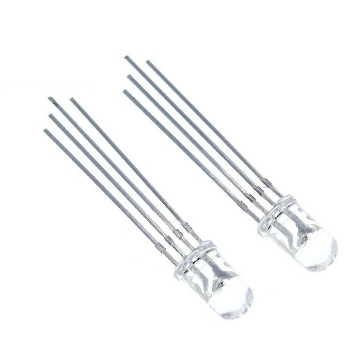
This is our 5mm Standard T-1 3/4 Type Full Color With Common Cathode LED.The Hyper Red source color devices are made with AlGaInP on GaAs substrate Light Emitting Diode.The Pure Green source color devices are made with InGaN on Sapphire substrate Light Emitting Diode.The Blue source color devices are made with InGaN on Sapphire substrate Light Emitting Diode.
Features:
Applications:
![]()
| Part No. | Chip Material | Lens Color | Source Color |
| DL-509RGBCA-001 | AlGaInP | Water Clear | Hyper Red |
| InGaN | Pure Green | ||
| InGaN | Blue |
Notes:
1. All dimensions are in millimeters (inches).
2. Tolerance is ± 0.25mm (.010″) unless otherwise noted.
3. Protruded resin under flange is 1.00mm (.039″) max.
4. Specifications are subject to change without notice.
Absolute Maximum Ratings at Ta=25℃
| Parameters | Symbol | Max. | Unit | |
| Power Dissipation | Hyper Red | PD | 65 | mW |
| Pure Green | 95 | |||
| Blue | 95 | |||
|
Peak Forward Current (1/10 Duty Cycle, 0.1ms Pulse Width) |
IFP | 100 | mA | |
| Ultra Red Chip Forward Current | IF | 25 | mA | |
| Pure Green Chip Forward Current | IF | 25 | mA | |
| Blue Chip Continuous Forward Current | IF | 25 | mA | |
| Reverse Voltage | VR | 5 | V | |
| Operating Temperature Range | Topr | -40℃ to +85℃ | ||
| Storage Temperature Range | Tstg | -40℃ to +100℃ | ||
|
Lead Soldering Temperature [4mm (.157″) From Body] |
Tsld | 260℃ for 5 Seconds | ||
Electrical Optical Characteristics at Ta=25℃
| Parameters | Symbol | Emitting Color | Min. | Typ. | Max. | Unit | Test Condition |
| Luminous Intensity * | IV | Hyper Red | 1600 | 3200 | --- | mcd |
IF=20mA (Note 1) |
| Pure Green | 2000 | 4000 | --- | ||||
| Blue | 1000 | 2000 | --- | ||||
| Viewing Angle * | 2θ1/2 | Hyper Red | --- | 25 | --- | Deg |
IF=20mA (Note 2) |
| Pure Green | --- | 25 | --- | ||||
| Blue | --- | 25 | --- | ||||
| Peak Emission Wavelength | λp | Hyper Red | --- | 632 | --- | nm | IF=20mA |
| Pure Green | --- | 520 | --- | ||||
| Blue | --- | 468 | --- | ||||
| Dominant Wavelength | λd | Hyper Red | --- | 624 | --- | nm |
IF=20mA (Note 3) |
| Pure Green | --- | 525 | --- | ||||
| Blue | --- | 470 | --- | ||||
| Forward Voltage | VF | Hyper Red | 1.80 | 2.20 | 2.80 | V | IF=20mA |
| Pure Green | 2.80 | 3.30 | 3.80 | ||||
| Blue | 2.80 | 3.30 | 3.80 | ||||
| Reverse Current | IR | Hyper Red | --- | --- | 10 | µA | VR=5V |
| Pure Green | --- | --- | 10 | ||||
| Blue | --- | --- | 10 |
Notes:
Typical Electrical / Optical Characteristics Curves
(25℃ Ambient Temperature Unless Otherwise Noted)
Hyper Red:
![]()
Pure Green:
![]()
Blue:
![]()
Reliability Test Items And Conditions:
The reliability of products shall be satisfied with items listed below:
Confidence level: 90%. LTPD: 10%.
1) Test Items and Results:
| Test Item | Standard Test Method | Test Conditions | Note | Number of Damaged |
| Resistance to Soldering Heat |
JEITA ED-4701 300 302 |
Tsld=260±5℃, 10sec 3mm from the base of the epoxy bulb | 1 time | 0/100 |
| Solder ability |
JEITA ED-4701 300 303 |
Tsld=235±5℃, 5sec (using flux) |
1time over 95% |
0/100 |
| Thermal Shock |
JEITA ED-4701 300 307 |
0℃~100℃ 15sec, 15sec | 100 cycles | 0/100 |
| Temperature Cycle |
JEITA ED-4701 100 105 |
-40℃~25℃~100℃~25℃ 30min,5min,30min,5min | 100 cycles | 0/100 |
| Moisture Resistance Cycle |
JEITA ED-4701 200 203 |
25℃~65℃~-10℃ 90%RH 24hrs/1cycle | 10 cycles | 0/100 |
| High Temperature Storage |
JEITA ED-4701 200 201 |
Ta=100℃ | 1000hrs | 0/100 |
|
Terminal Strength (Pull test) |
JEITA ED-4701 400 401 |
Load 10N (1kgf) 10±1sec |
No noticeable damage | 0/100 |
| Terminal Strength (bending test) |
JEITA ED-4701 400 401 |
Load 5N (0.5kgf) 0°~90°~0° bend 2 times |
No noticeable damage | 0/100 |
| Temperature Humidity Storage |
JEITA ED-4701 100 103 |
Ta=60℃, RH=90% | 1000hrs | 0/100 |
| Low Temperature Storage |
JEITA ED-4701 200 202 |
Ta=-40℃ | 1000hrs | 0/100 |
| Steady State Operating Life | Ta=25℃, IF=30mA | 1000hrs | 0/100 | |
| Steady State Operating Life of High Humidity Heat | Ta=60℃, RH=90%, IF=30mA | 500hrs | 0/100 | |
| Steady State Operating Life of Low Temperature | Ta=-30℃, IF=20mA | 1000hrs | 0/100 |
2) Criteria for Judging the Damage:
| Item | Symbol | Test Conditions | Criteria for Judgment | |
| Min | Max | |||
| Forward Voltage | VF | IF=20mA | --- | F.V.*)×1.1 |
| Reverse Current | IR | VR=5V | --- | F.V.*)×2.0 |
| Luminous Intensity | IV | IF=20mA | F.V.*)×0.7 | --- |
*) F.V.: First Value.
Please read the following notes before using the product:
Customer must apply resistors for protection, otherwise slight voltage shift will cause big current change (Burn out will happen).
2.1 Do not open moisture proof bag before the products are ready to use.
2.2 Before opening the package, the LEDs should be kept at 30℃ or less and 90%RH or less.
2.3 The LEDs should be used within a year.
2.4 After opening the package, the LEDs should be kept at 30℃ or less and 70%RH or less.
2.5 The LEDs should be used within 168 hours (7 days) after opening the package.
Each terminal is to go to the tip of soldering iron temperature less than 260℃ for 5 seconds within once in less than the soldering iron capacity 25W. Leave two seconds and more intervals, and do soldering of each terminal. Be careful because the damage of the product is often started at the time of the hand solder.
Repair should not be done after the LEDs have been soldered. When repairing is unavoidable, a double-head soldering iron should be used. It should be confirmed beforehand whether the characteristics of the LEDs will or will not be damaged by repairing.
Static Electricity and surge damages the LED. It is recommended to use a wrist band or anti-electrostatic glove when handling the LED. All devices equipment and machinery must be properly grounded.
Contact Person: Mr. Chen
Tel: 86-755-82853859
Fax: 86-755-83229774
| Factory Address:6th Floor,D Building,Weihuada Industrial Park,Huaning Road,Dalang,Longhua District,Shenzhen City China | |
| Sales office:2403 Room, International Technology Building, NO 3007, Shennan Middle Road, Futian District, Shenzhen City, China,Zip:518033 | |
| +86-755-82853859 | |
| sales@doublelight.com.cn | |